A Raytracer in Python - Part 6 - Cameras
In the latest commit for the raytracer, I added cameras. The design changed so that now the responsible for rendering is the camera object. Actual cameras are specializations of an abstract class BaseCamera, which holds common information about positioning. The BaseCamera is then specialized into two concrete classes:
- PinholeCamera is a camera where rays are shot as diverging from a single point, called the eye_point. This allows perspective, which was not present previously as the rays were emerging from the ViewPlane pixels.
- LensCamera is a camera that simulates depth of field, that is, focus/out of focus. Contrary to the PinholeCamera, where everything is in focus, LensCamera allows different focusing. Objects that happen to be on the "focal plane" are in focus, while objects that are outside (either closer or farther from the camera) present less defined details proper of an out-of-focus object. To perform this effect, we need the random sampling on a disk implemented in the previous post.
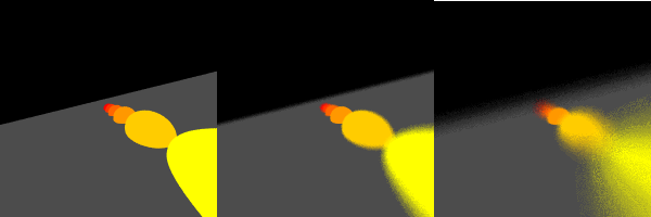
The following picture shows how LensCamera performs. A set of hemispheres are deployed along a line. The camera is above them, slightly angled and with a roll angle appreciable from the horizon. In all three cases, the orange central sphere is focused, as the focus plane has been set to fall on the sphere's position. Note how other objects are in focus for a Pinhole camera (left picture) which has no depth of field by construction, and become more out of focus as the lens size increases (1.0 in the center picture, 5.0 in the right one)
Other cameras may technically be possible: the book goes further in deploying fisheye and stereoscopic cameras, but I am not interested in them. I think the pinhole and lens camera are flexible enough for quality renderings and my desire to learn.
One important feature of the Camera system is that it requires the definition of local coordinates on the camera itself. The three vectors defining this set of coordinates, called u, v, w in the book, are obtained by building an orthonormal basis using the cross product between the observation vector (the vector between the "eye" of the camera and the look_at point) and an "up" vector, our default being in the same direction as the y axis. Doing the cross product of these two vectors (observation and up) produces the third remaining vector of the orthogonal basis centered on the camera. However, if the camera looks straight up, or straight down, the cross product is zero and we obtain a singularity, losing one degree of freedom (a condition also known as gimbal lock). The book proposes to detect this condition and treat it accordingly, by either overriding the specification and setting the vectors to an arbitrary, well defined alternative, or by "juggling" the up vector out of alignment so that the third vector is still defined. I decided for the third option, ignore the problem, as I am not going to use gimbal locked configurations for now, but it's definitely a problem to add to the todo list.
With this post, I take a temporary break from the raytracing business. I may add optical effects such as reflections, refractions, materials, lights, but the point is that the amount of rays that must be propagated for these effects to show tends to be very high. I want to venture into CUDA, and therefore I will switch my attention to CUDA programming from now on, integrate it with the raytracing later on, then go back to light effects at a later stage. I will implement light effects first in python, then use CUDA to achieve the same results. My aim is to have fun, test CUDA/C/Python integration, compare performances, and provide a fully python raytracer with optional C/CUDA high-performance code to achieve the same task. For CUDA tinkering, I will switch back to my old friend, the mandelbrot set.