Building my own keyboard - Part 3
After the initial exploration, let’s start small. The first step is to create a small 2x2 matrix and have arduino push out i2c data for the scan codes.
I am following the excellent guide from the bald engineer and I managed to create this.
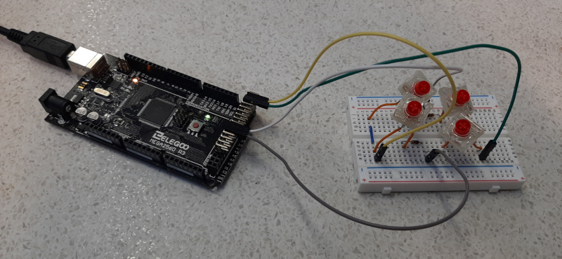
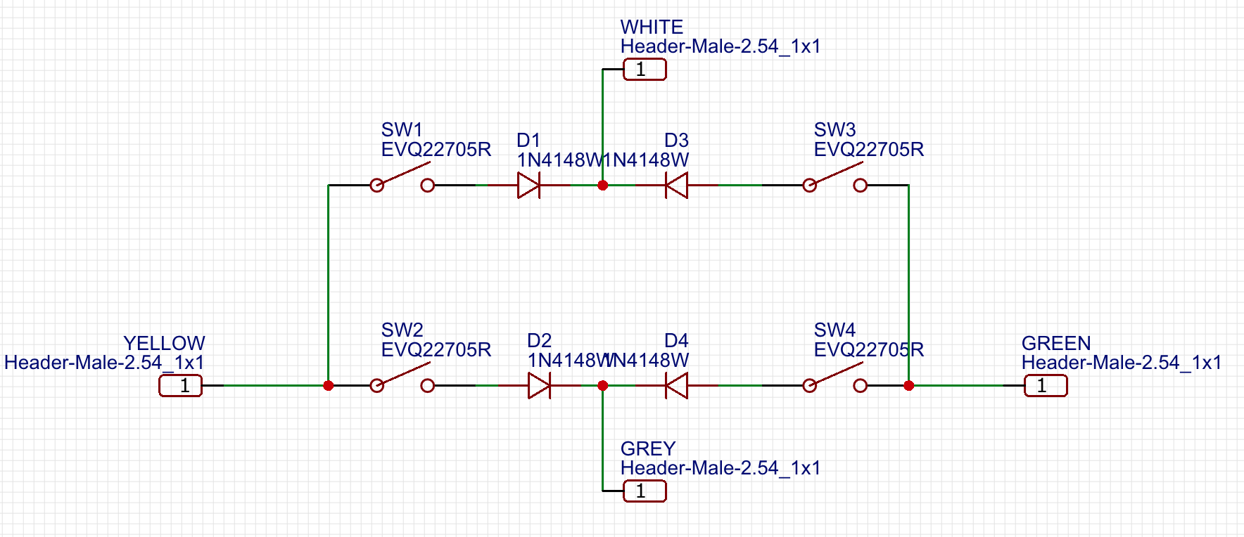
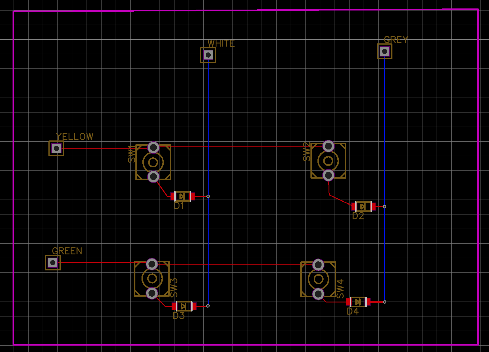
The matrix is configured from pins 22 (yellow) and 24 (green) for the rows, and pins 38 (white) and 40 (grey) for the columns. The firmware is trivially scanning and returns the appropriate scan code (for now of keys QWAS), for now through serial for debugging. To communicate with the raspberry pi master we will need a different approach. The circuit can be summed up more or less as this:
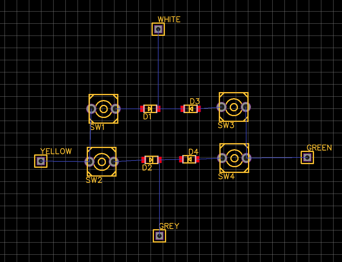
If we create the PCB from the above schema, we obtain the following connectivity network
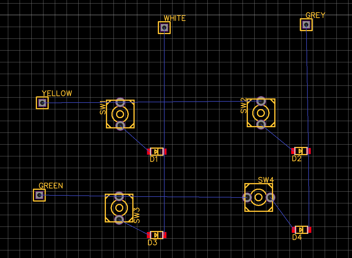
If we reorder and rotate the components we obtain this
And if we finally trigger the autorouter we get this layout for the copper traces
Which points at the general pattern I’ll have to assemble.
Communication between the arduinos and the RasPi
To connect the two arduinos to the raspberry pi I will use I2C. It’s a simple bus that needs a very limited number of pins. By design, I2C requires that the master is always initiating the communication, and the slave receives that communication and optionally replies. No problem, I thought: the two arduinos will be masters, and the RasPi a slave, and I2C supports multimaster configuration.
Unfortunately it’s not that simple: I opened a question on Raspberry PI stackexchange, and apparently I can really only have one master. Most importantly, the raspberry Pi kernel does not support slave mode. This is also confirmed here. As a result, the only option I have is the following:
- set the Raspberry Pi as master
- set the two arduinos as slaves, each on a different bus (for practical reasons).
- When a keypress is issued, the arduino firmware will
- trigger an interrupt line to the pi to warn that there is data to read.
- the pi interrupt handler sets the pi to master receive mode.
- the arduino uses the Wire library to send data about the keystroke, with the payload being the scan code.
This dance seems complicated, and it is, but it becomes even more complicated by the following problems:
- the pi might be busy when the arduino is ready to send.
- there is a time delay from when the interrupt pin is enabled to when the arduino enters slave send mode.
- the pi might have to respond to a second interrupt while it’s still in the interrupt handler (e.g. if the other half of the keyboard also wants to send a keypress)
- the pi or the arduino might crash, hang or run out of resources.
Now, it’s a keyboard, not a nuclear reactor, but still I find it interesting to play with these kind of problems. There’s a lot to learn.
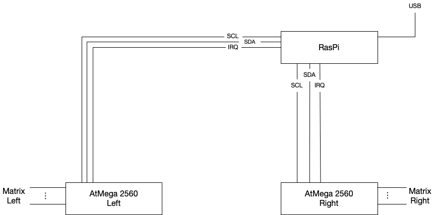
In any case, my final design will be as depicted in the picture below
More layouting and baseplate design
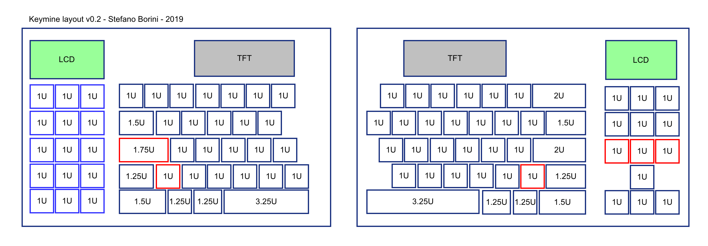
I analysed the layout as I was getting ready to create the prototype baseplate. I went to and created this layout, using the keyboard-layout-editor website.

I link the layout for future tinkering and modifications. I then decided to split the two as separate JSONs as they will need two different base plates and circuits, so I have separate files for the left and for the right
I had to perform a few changes to my original design. First, I had to change the length of the spacebars to 3u, because the builder program I am using for designing the plate did not add stabilizers for intermediate length. It was either 3u or 4u, and I chose 3u. Second, I had to tinker the math here and there to ensure the proper alignment.
To generate the baseplate, I fed the raw data into the Swillkb online builder to obtain this design:

This layout is very approximated. I considered nothing more than the hole positioning and the general understanding of the process, but I will need to refine it a bit.
Laser cutting the layout
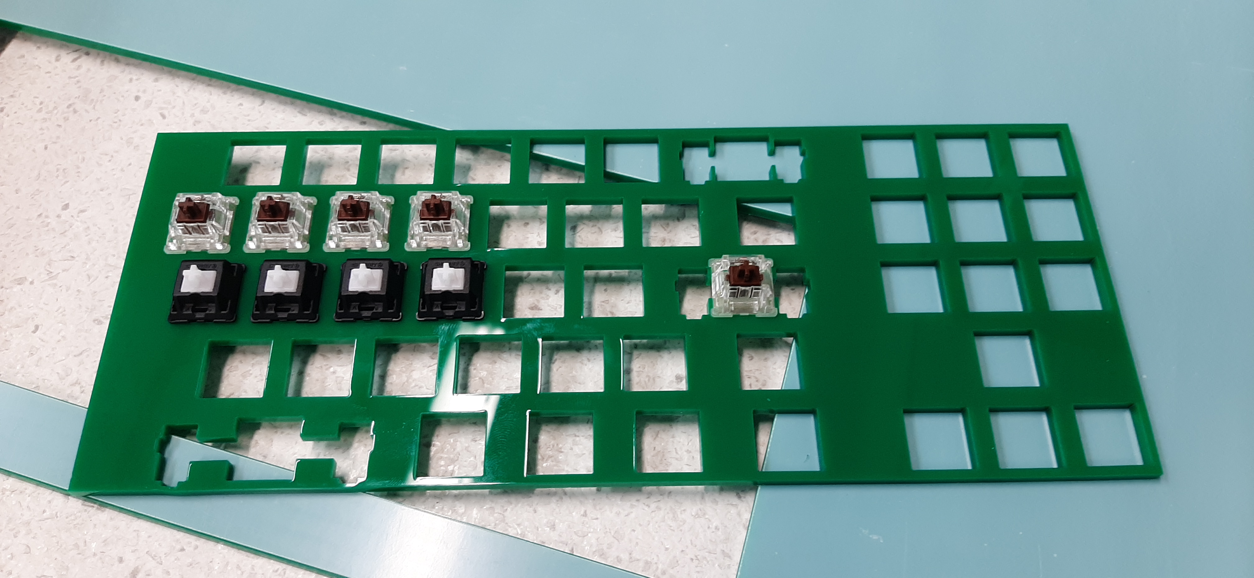
I then used a laser cutter to obtain this baseplate for the right hand:
Some observations:
- I must use 1.5mm acrylic. The cut in the picture uses 3mm acrylic, which is too thick to secure the retainer clips in the cherry switches. I will eventually have to redo the whole thing for when I’ll have to cut the aluminum baseplate, but for prototyping 1.5mm acrylic is what I need.
- I need to adjust the kerf. The laser has no infinitely small thickness, so one has to adjust the position of the laser considering its thickness. For this cut, the kerb was set to zero, but I will have to adjust it, as the keys are loose.
- Corners tend to melt excessively. This is not a major problem, but it can become one for those parts that are very thin, such as the thin borders between the backspace key switch and the stabilizers.