Building my own keyboard - Part 4
Thinner acrylic
One of the problem I had at makespace is that only 3mm acrylic was available. Unfortunately, as said previously, the Cherry MX keycaps have locking tabs that only engage at 1.5mm. The keys will pop out with anything thicker.
One of the main issues with 1.5mm acryilic is that it’s very wobbly. In general, base plates are made of aluminum or steel, with a preference for the former. Typing feeling and longevity of the keyboard depends on the flexibility of the base plate: too bendy and it will feel mushy and put stress on the solder; too rigid and it will feel like having an apple macbook, the worst keyboard currently in production.
Unfortunately, laser cutting aluminum is expensive and I can’t do it at makespace, but I might have a workaround to remedy the flexibility of the 1.5mm acrylic. If you observe the keybow, you will notice that there’s a wide channel between the baseplate, the PCB, and the two rows of keys.
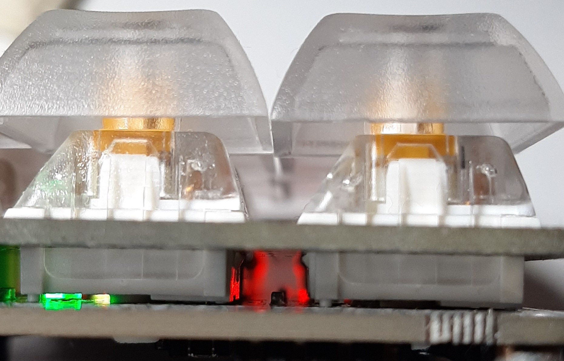
I can use this clearance, that will also be available in my keyboard, to add a second 1.5mm baseplate layer that will stiffen the whole structure. Maybe?
Connecting Arduino with the Raspberry Pi
Now that I have a working arduino firmware that scans the keys and sends the keycodes, it’s time I start to think of the raspberry pi and its connection with the arduino(s). I decided to use I2C, as mentioned before, plus an interrupt signal due to the nature of master/slave communication in I2C.
First, I reworked the code to examine the difference between the key pressed before and after an event, and to store this differences in a buffer. When there is a change (e.g. some keys passed from keyup to keydown) the Arduino will trigger an interrupt and expect the master to come calling to retrieve the content of the buffer. The interrupting pin will be pin 23.
I also setup a Raspberry Pi zero, installed a raspbian,i enabled the I2C support according to the documentation, connected SCL and SDA between the two devices, and the IRQ line into a RasPi GPIO. In principle, this should work, and the first line of validation is by means of invoking
i2cdetect -y 0
Of course it did not work. First, apparently recent RasPi want to use i2c-1, so the correct invocation is
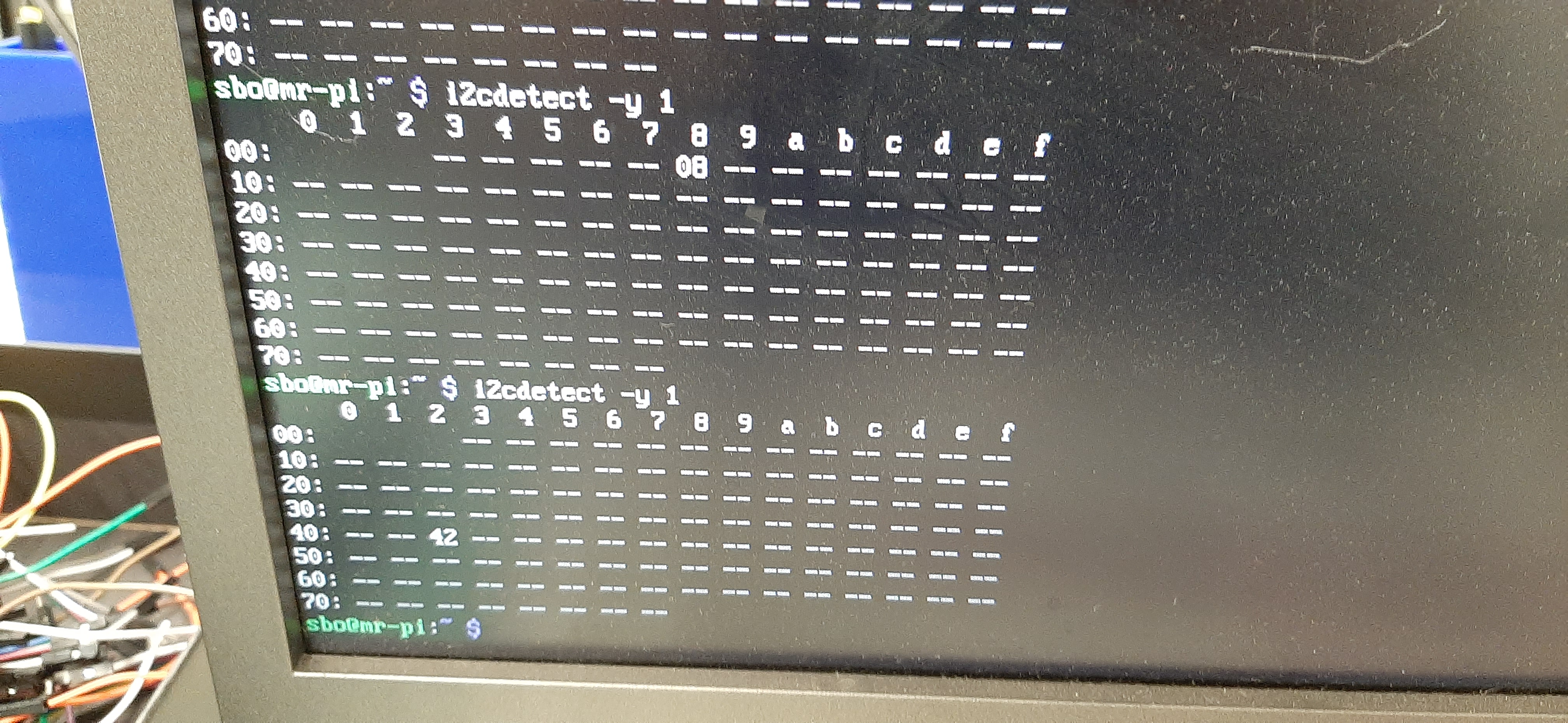
i2cdetect -y 1
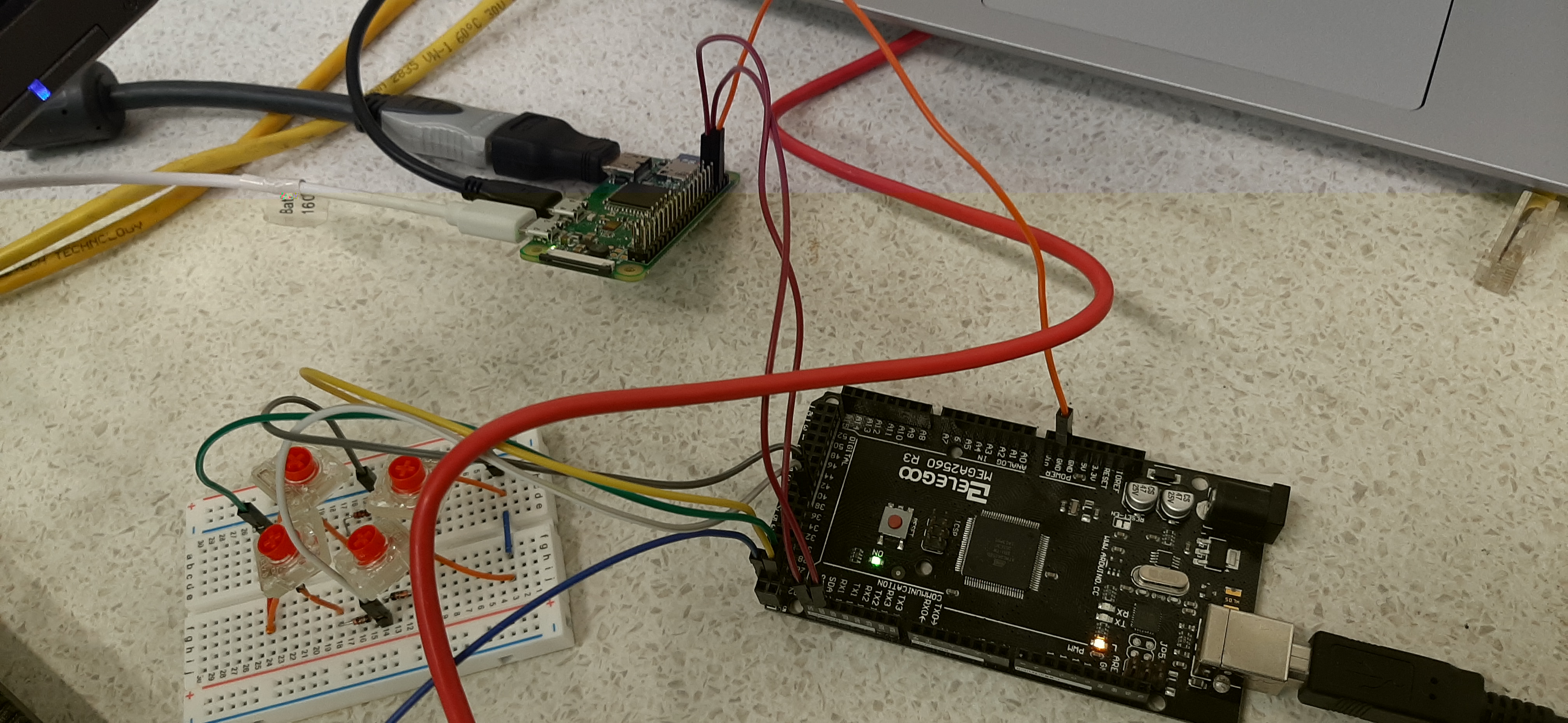
But there was another problem, as the response did not show any device. I started checking for things that might be broken or disconnected, but then I realised that there might be an issue due to the arduino and the raspberry pi not sharing the same ground. I connected the grounds of the two boards with an additional cable (Note: the IRQ blue wire is disconnected in the picture for unrelated reasons)
and finally I get an answer on device 0x42 (yes, I know that it’s not 42 in decimal)
After this I wrote a small script in python for the RasPi to see if I get a signal. And I do:
Now, the next step is to actually send data. One thing I quickly realised is that I2C is not really supporting a slave that might send an undetermined amount of data. The master setup requires that the number of bytes it expects to receive is specified. As a result, my protocol design must send a fixed length packet. Another issue I discovered is that I2C maximum transmission size is 32 bytes. Hence, in these 32 bytes I need to store information about the keys pressed and released during the latest scan that sees a difference.
The most trivial implementation is to use two bytes per key, the first byte being the scancode, and the second byte being for keyup or keydown. This allows me to deliver 16 simultaneous keypress changes. I could devise a better protocol but frankly I think it’s good enough for all practical cases of keyboard headslamming. This of course assumes that I have a “Null scancode”, otherwise I will have to send how many of the 16 pairs is actually used, wasting one byte. A quick glance to the HID scan codes, page 53 gives that 0x00 is in fact reserved and used as not a physical key. Excellent. So my packet will be 32 bytes, divided as 16 byte pairs with the first one the scan code or 0x00 for no key, and the second one 0x00 for keyup, 0x01 for keydown.
It is important to remember that the actual USB HID will be the raspberry pi. The external world will not know of the existence of the arduinos. It is just for my personal simplification, and because it makes sense, that the arduino generate the USB HID scan codes. The raspberry pi will just forward them.
The PCB with Kailh hot plug connectors
My initial attempt at EasyEDA editing of the PCB was not particularly successful, and I had to redo the same thing many, many times. My first iteration was just to get an idea of the complexity. I used the Cherry Switch from the EasyEDA library and a few diodes, imported the baseplate image as documentation (so that I could get a reference of the positions) and arranged the switches in the proper places. I tried manual routing mostly because I wanted to get some practice with the controls. Additionally, the online router was too unreliable, so I just downloaded the local one.
The next step was to use Kailh hot plug connectors. These connectors are Cherry compatible and save me the pain of soldering the thin button leads. I already have a bag of these connectors.
Now the main problem was to create a PCB module for these switches. I am getting to the end of the story quickly, but I discovered that a solid region in EasyEDA is not equivalent to a pad. You can’t connect to a solid region, even if the copper is exposed. You must create a pad. If you don’t want a hole, simply limit the pad to a single layer (top or bottom). This discovery came at the end of a painful debug session where the autorouter failed with an unclear message. Also be aware that creating your own PCB module with precise geometry positioning is an absolute pain with EasyEDA. I asked a friend and he reported me that the world is not better with Eagle. I haven’t tried KiCad. Also, EasyEDA has the nasty habit to crash every now and then during high zoom in.
Nevertheless, after painful adventures with the autorouter that gave rather nasty results, I finally managed to get this PCB for Keymine version 1 left

I then exported the Gerber file, uploaded it to jlcpcb and finally ordered the PCB. Now we wait.
The keycaps
There are two main families of keycaps: DCS and DSA. (There is also a third, SA, but it’s not very frequently seen)

The profile, the angle and the shape of my current keyboard is DSA, so I will aim for this shape. I am planning to order the vast majority of keycaps from https://pimpmykeyboard.com/ however they don’t seem to have 3 spaces DSA spacebars, which is what I need. They also seem to only have Alps mount. I need a Cherry mount. After some investigation, it seems that finding a 3u spacebar is pretty much a lost cause. Some information points me in the direction of shady chinese suppliers, something I am unwilling to pursue.
I suspect an option would be that I make use of my utter lack of expertise in 3d printing and CAD drawing and try to hack this thingiverse spacebar. My main concern is the texture, but it might end up ok. I could try to do acetone vapor smoothing to improve it.