Building my own keyboard - Part 5
Baseplate and new (larger) prototype matrix
I managed to get my hands on the 1.5 mm acrylic and build a double layered 3mm thick baseplate. It was horribly expensive, and unfortunately only available in transparent. I say unfortunately because LEDs are no longer an option, as they would shine through the baseplate and not illuminate precisely one key. Aluminum is still an option I am considering, but for now LEDs are not my top priority.
I created the baseplate by cutting two layers: the first layer as normal, and the second by enlarging slightly the holes for the switches. I just used the laser cutter software to do it. Then, I used cyanoacrylate glue to stick the two layers together. This creates a 3mm sandwich that has lips in each switch hole. On these lips the Cherry switch locks perfectly.
The main problem with this method is that cyanoacrylate is very fast curing. I need a slower curing glue for the bigger baseplates. The most appropriate glue for this task seems to be Tensol 12 which has an initial setting time of 3 hours and a final setting time of 24 hours. Not perfect, but I can deal with it.
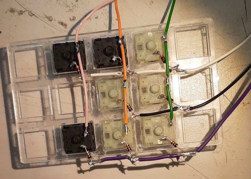
I then decided it’s time to move forward to a larger matrix from the current 2x2 I have on the prototype breadboard, so I used the small baseplate, added the switches I had laying around, a handful of 1n4148 diodes and here it is:
Switches shipment
I just got the shipment of switches. I opted for Gateron as finding Cherry MX turned out to be quite hard. As far as my experience goes, they are pretty much equivalent in quality, specs, and shape. They are also cheaper.
The best source for Cherry MX turned out to be this German shop but I got 104 Gateron for 24 pounds, which is a fourth of the price of the equivalent Cherry MX set.
While I was looking for places where to buy switches, I also found the following shops
- https://www.switchtop.com/
- http://www.ukkeycaps.co.uk/
- https://candykeys.com
Connecting Arduino with the Raspberry Pi
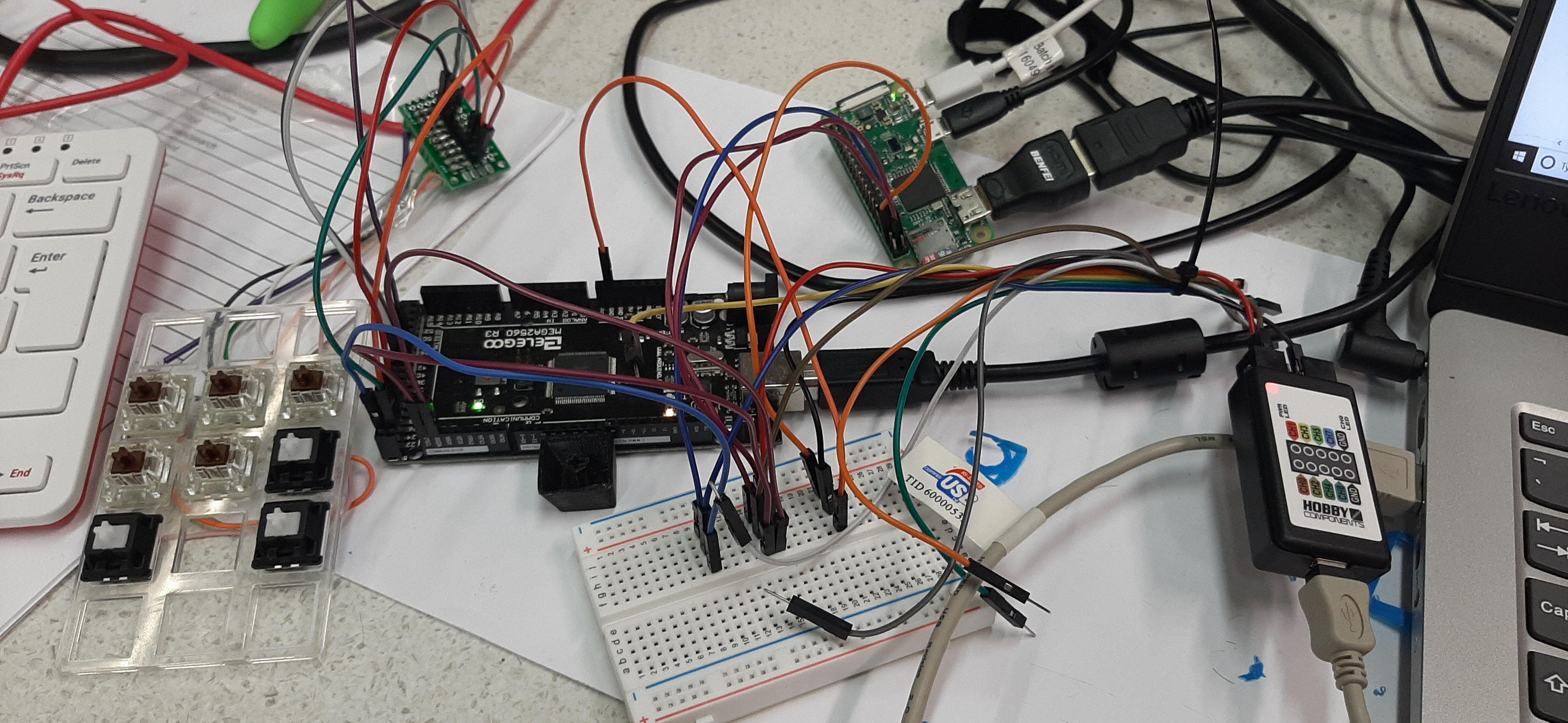
With the new matrix soldered and ready, it’s now time to stress the firmware and the raspi, including the actual transmission of data via I2C. First, I connected the new matrix with the arduino, and the arduino with the raspberry pi. In the image, I also added a breadboard and a logic analyser, for reasons that will become clear in a moment
I then modified the arduino to use the wire library and send 32 bytes of data containing the currently pressed or released keys, with a simple encoding: the first byte is the scancode, the second is 0x00 if the button has been released and 0x01 if it has been pressed. This is repeated for 16 times to allow for up to 16 simultaneous events.
Unfortunately, it doesn’t work. I think I know why, but first let’s see the behavior: occasionally, I get incorrect data in the stream. This is pretty much guaranteed to happen when multiple keys are pressed. This picture shows what the raspberry pi is receiving.
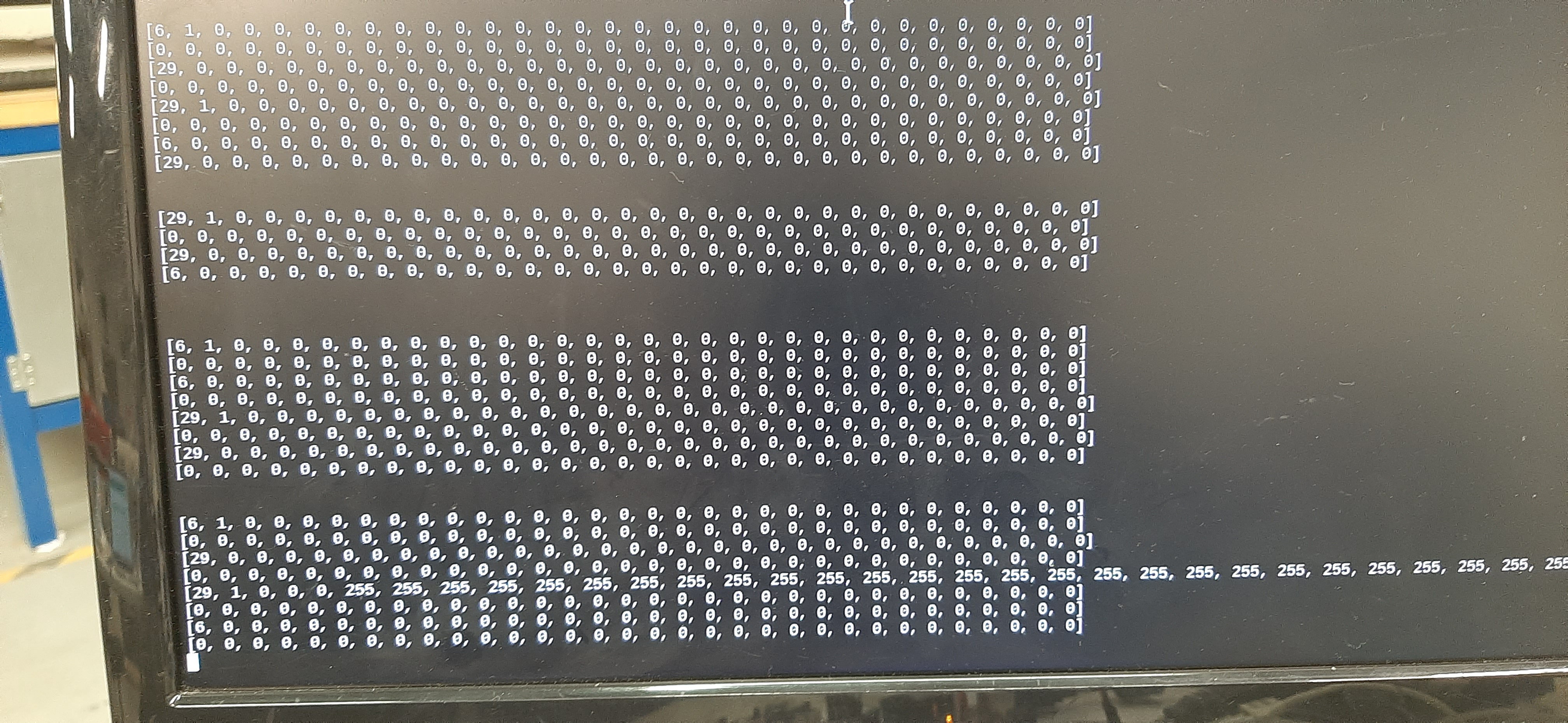
As you can see, there are occasional 0xFF (255) that are sent for no reason. Additionally, sometimes there is an array that is all zeros 0x00. This is also not possible according to the protocol. In order to debug the problem, first I wanted to see if that false data was actually in transit, hence the logical analyser. It turns out that they do indeed go through the wire
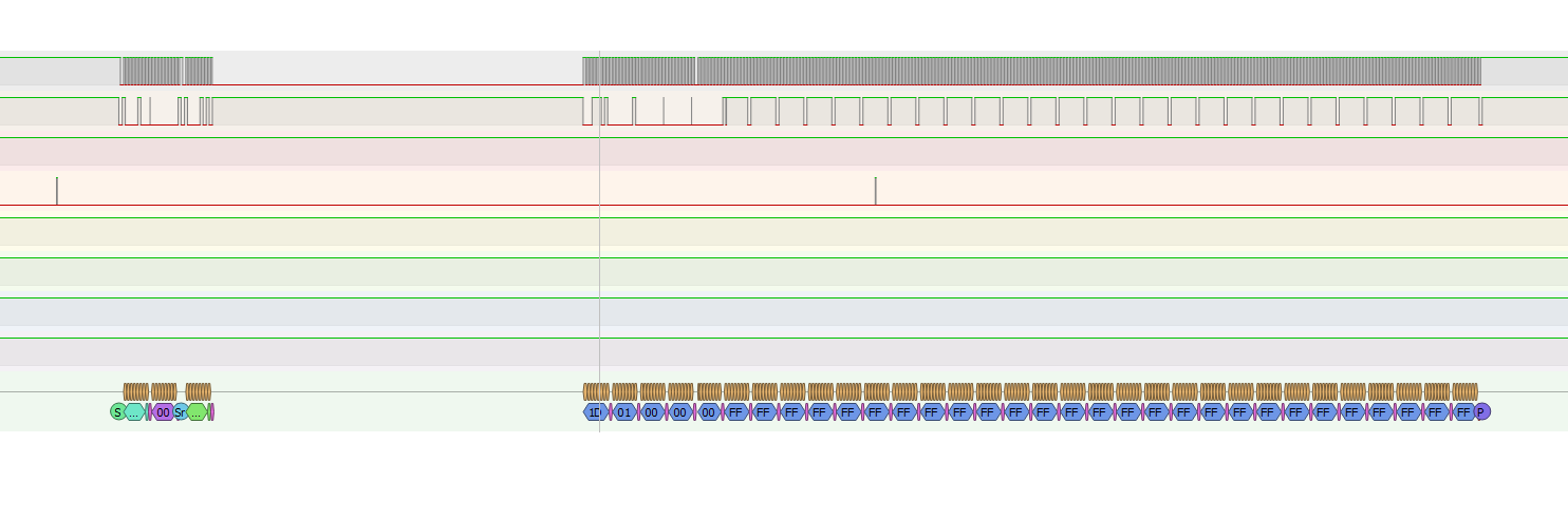
So the arduino is sending it. However, I never actually populate the array with those values, and if I print them to Serial just before they are sent out by the arduino, they are all zero. What gives?
What gives is that my C is old, I am old, and I make mistakes. memset wants the size in bytes, so this
memset(buf, 0x00, 32)
should really be this
memset(buf, 0x00, 32*sizeof(byte))
For shame! But troubles are far from over. I reworked the code a bit because a few potential race conditions with the interrupt were present, but it still does not work and produces odd results. This time however I don’t think it’s my fault. I’ll write more in the next post, but I might have to dig into the i2c kernel driver.
PCB
The PCB arrived, and they are a thing of beauty.
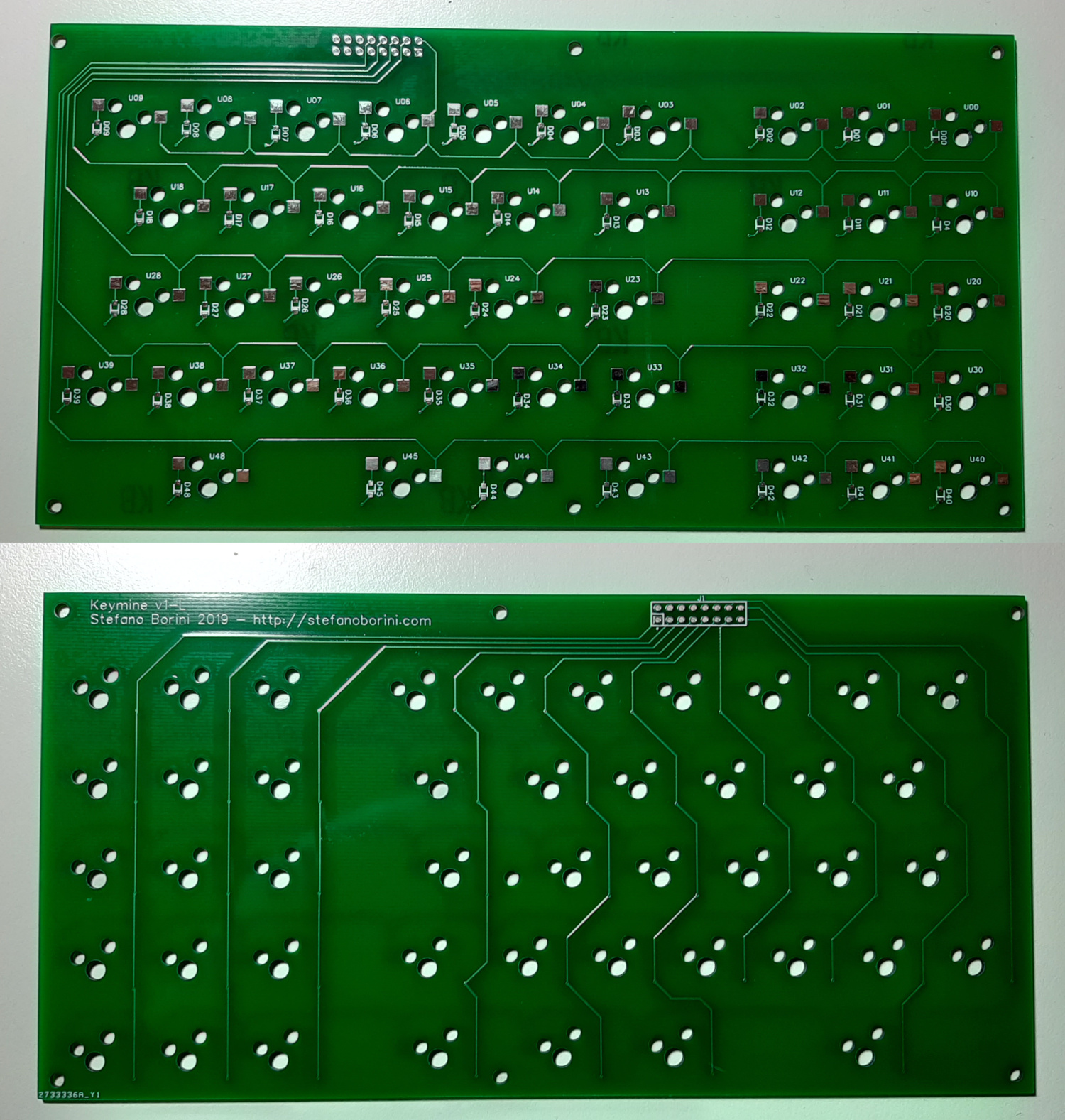
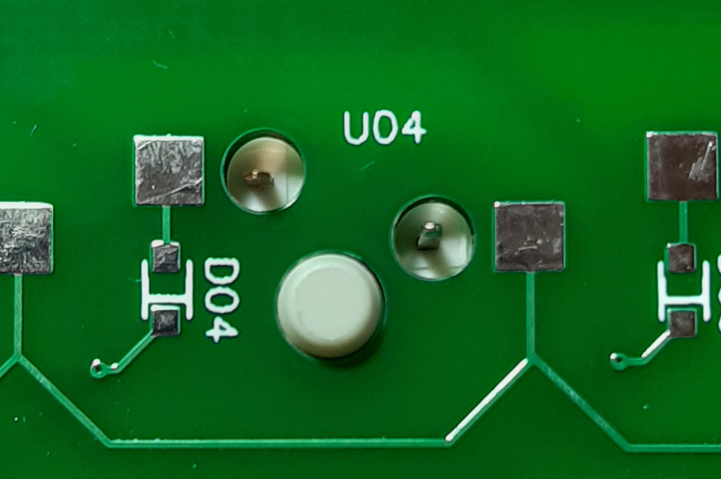
The buttons fit perfectly. As you can see, the central pin sits perfectly in the middle hole, and the two contacts are perfectly aligned with the hot-swap holes.
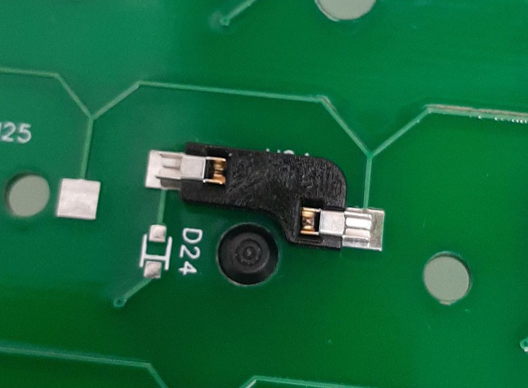
And it also perfectly matches the Kailh hot swap contact
Unfortunately, one minor snag is the position of the top-left screw hole, which is definitely too close to the border, and misaligned with the other holes. This is the classic little, blatant mistake that gets uncaught no matter how much you check. I will fix it, but I doubt I will get a replacement PCB. I’ll probably drill the hole myself. I have five PCBs of the left side, in case I want to make more keyboards. This is the unintended consequence of a minimum order of five.
The keycaps
To explore the viability of 3d printing the 3u spacebar, I printed an ABS button from the thingiverse, then applied acetone vapors to smooth it. I used a 0.06 mm high resolution print, and this was the result
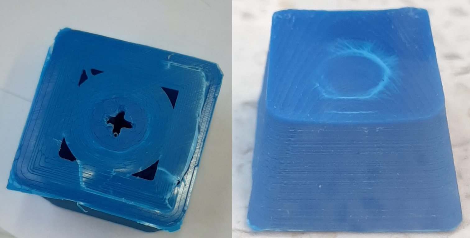
Setting aside the color, there were a couple of major issues: the first one is that the accuracy of the cross-shaped hole was very, very poor, leading to a result that did not fit the switch. Despite various attempts, I only managed to break the central rod. This means that I will have to account for this poor accuracy and rework the 3d model to make it more tolerant to it.
I then setup a small acetone chamber with an upside down glass, a napkin with some acetone, and the key at the bottom.
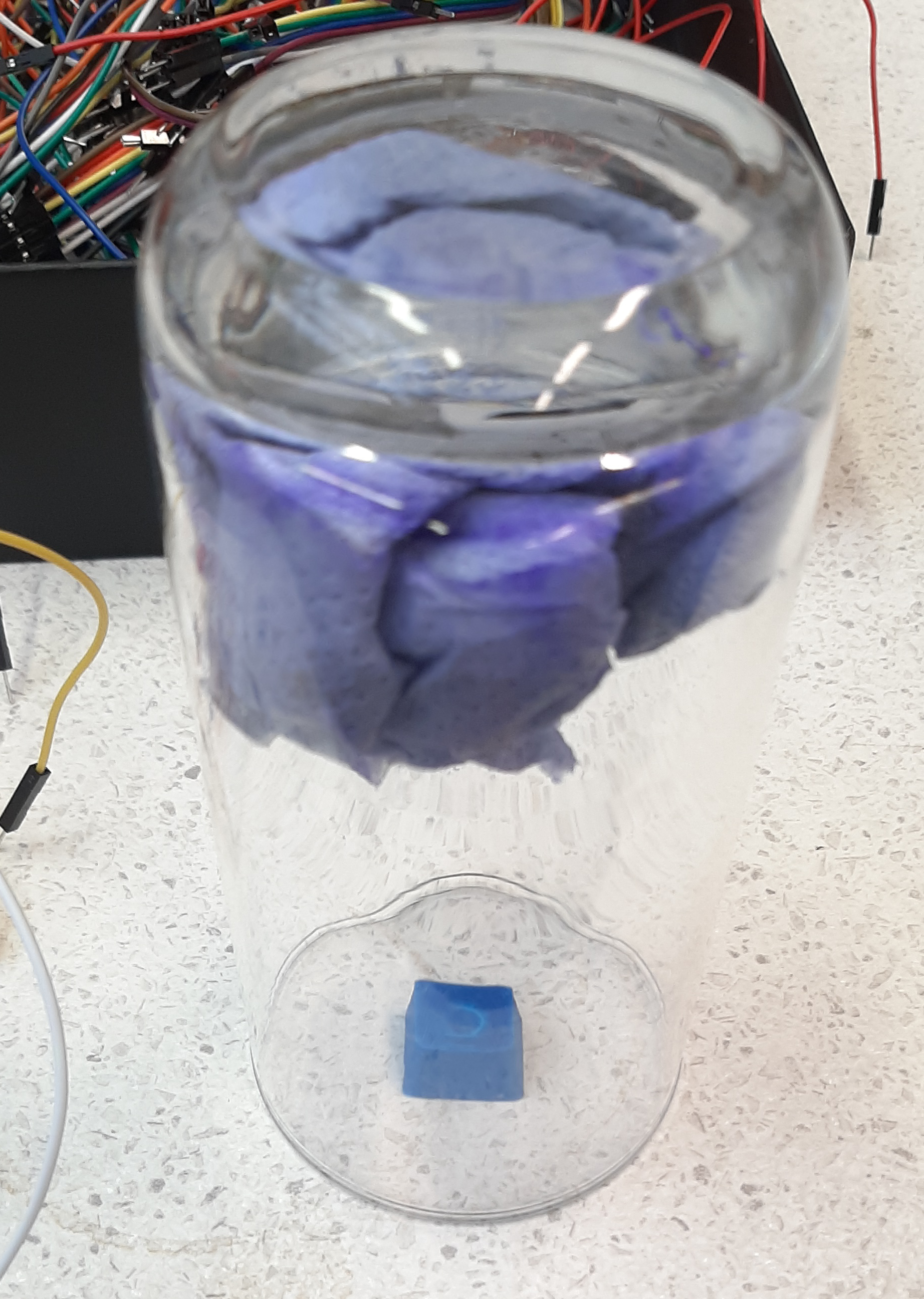
I then left the key in there for a time that I considered adequate, but turned out to be probably excessive: 30 minutes. The resulting key is definitely smoother, but it’s clearly not a very appealing result.
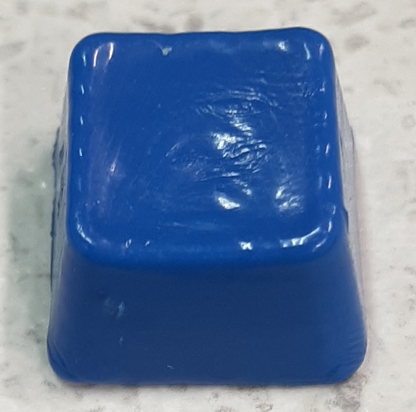
I might have to find a different solution.