Building my own keyboard - Part 6
Baseplate
I laser cut the complete baseplate. The files are available here I clearly screwed the screw space, as there’s not enough space for setting them. It needs rework. In any case, the two layers must be glued together with Tensol 12, a fast curing glue tailored to acrylic. To verify its strength bond, I applied a small amount on two scrap strips of acrylic. I let them cure for 24 hours, and then tried to separate them. It was much stronger than I could even remotely think. I tried to shear separate them by using pliers and pulling in opposite directions with the help of another person. The acrylic snapped first.
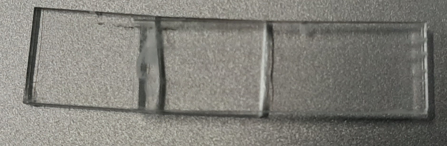
Without a doubt it’s a much stronger bond than cyanoacrylate, which is well known to have poor shear strength. I don’t expect to shear the baseplate, of course, but it’s good to know that Tensol 12 lives up to its promises. It stinks horribly though. So it is safe to say that tensol 12 is indeed an excellent bonding agent for acrylic, and it’s perfectly transparent too. Unfortunately, I also realised that the actual time from application to solid is in the order of 15-20 seconds, not hours as I believed. Longer than cyanoacrylate, but still very small to allow for proper gluing and setting of the two halves of the baseplate. My first attempt was far from perfect, as you will see soon, but I will come up with a solution for rapid application at a later stage.
PCB
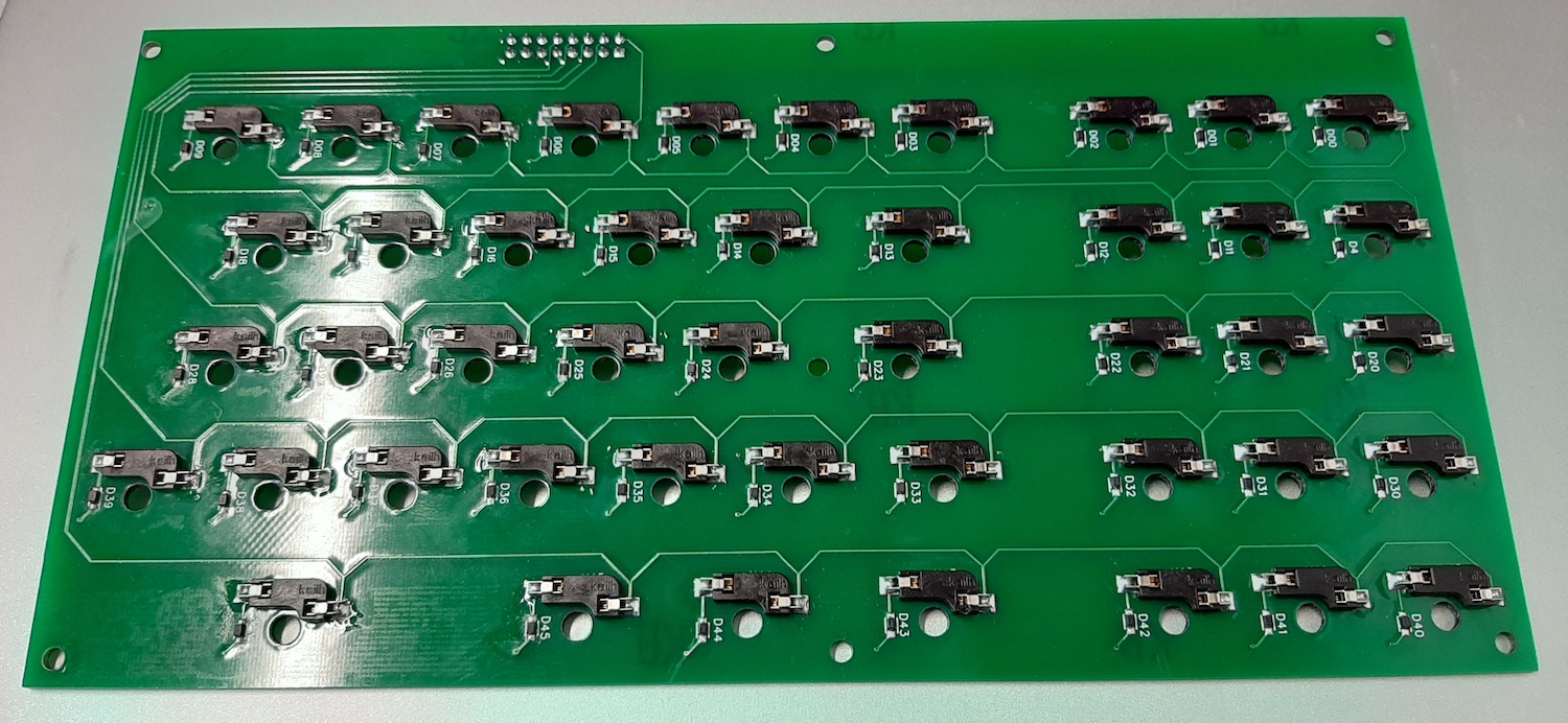
Soldering the PCB components took me a whole day, but I found myself strangely absorbed at the zen-like activity of soldering with a microscope. I thought it was much harder, but with a steady hand, a good technique with the solder, iron, and tweezers, and some good tune, I managed to solder all the diodes and the kailh hot-plugs.
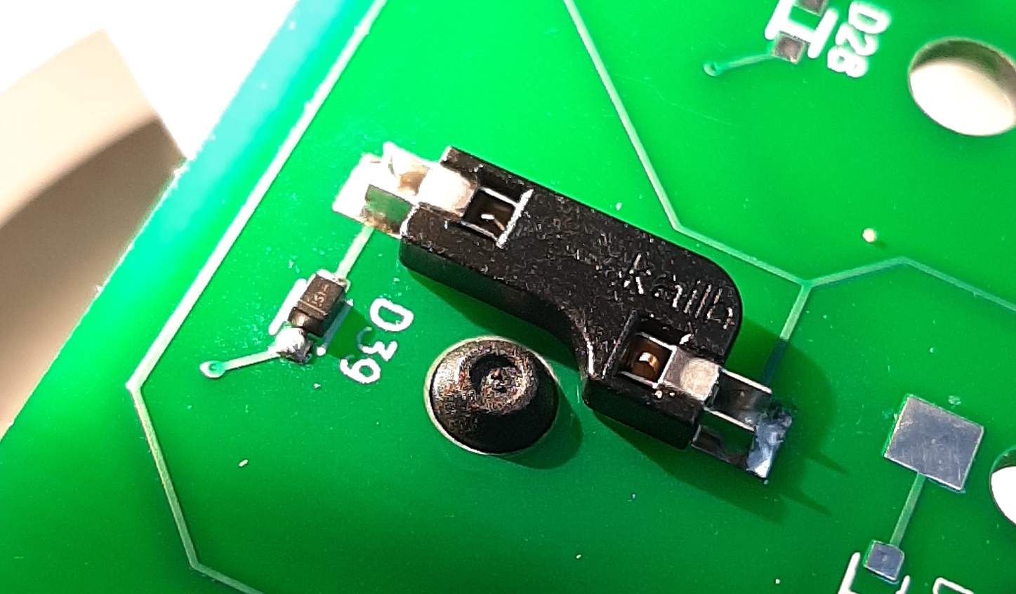
It is of particular importance to keep close attention to the diode directionality, indicated by a small yellow band. Keep into account that these diodes are the size of a sesame seed, and the contacts are the size of a grain of sand.
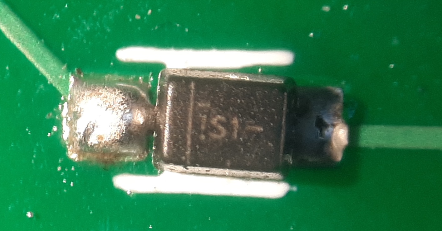
The final result is very pleasing:
That said, I doubt I will use the kailh hot-plugs in the final model. They were hard to find, and they provide little advantage for the final product, besides the ability to replace a switch easily. But seriously, I don’t think I’ll ever replace switches in the finished model. I do however want to keep this option for the current prototypes, so I can reuse the switches in later prototypes and finished product. The result is that I will have to rework the final PCB to just provide through-hole solder pads for the switches.
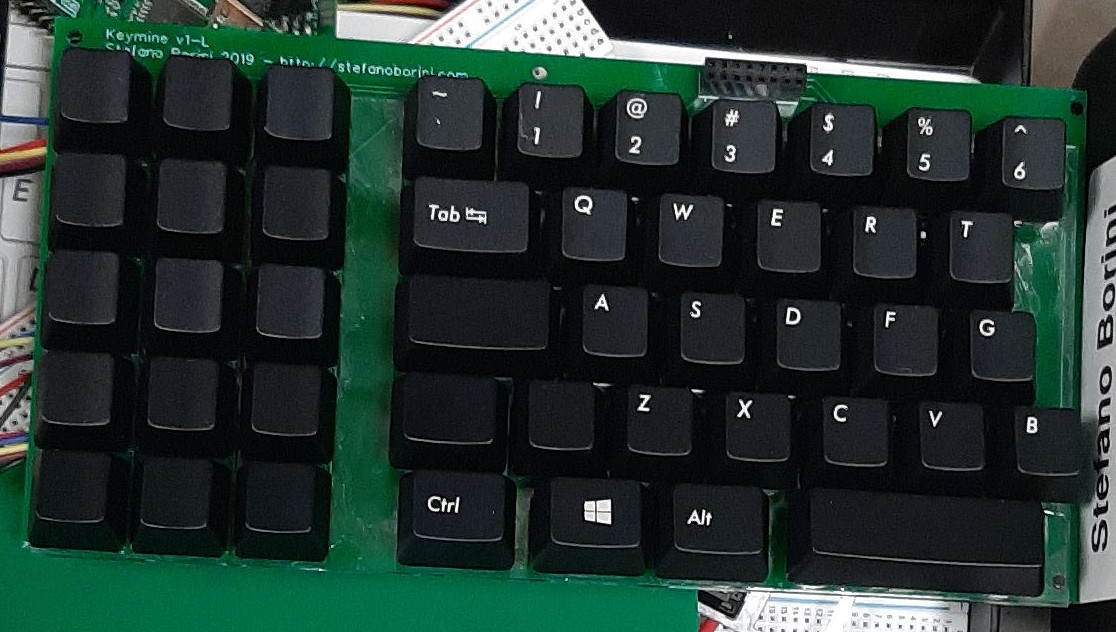
After adding the baseplate and the switches, it’s now time to do the final assembly of the left side prototype:
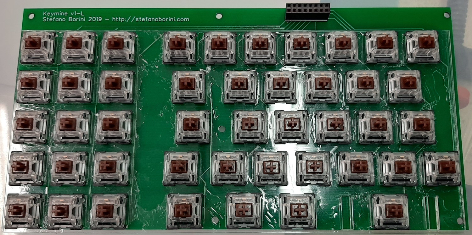
Note how the baseplate tensol application was far from perfect, but despite this I am pleased with the result. Except that, well, I made a big (but overall unimportant) whoopsie: the switches are upside down! maybe? maybe not? It’s unclear. Let me explain. If you look at the image from wikipedia of a cherry keyboard you will note that the slot for the LED is on the bottom. This article also shows pictures of an official Cherry keyboard with the slot on the bottom]. However, if you look at keyboards that are backlit, the LED is at the top. The switches are completely non-directional, but the LED position is important as the letter are translucid and the light needs to shine through. My keyboard has no backlight, but I might consider adding individually controlled LEDs later on.
#/media/File:Cherry_MX_Blue_Switches.jpg)
Debugging arduino/raspi connection woes
I realised I have made another pretty large whoopsie, this time with the connection. I am not sure if this is the source of my current issues with the I2C, but it certainly needs fixing. The arduino mega2560 is operating at 5 volts. The raspberry pi at 3.3v, and its pins are not 5v resistant. There’s a chance that I might have destroyed the raspberry pi GPIO, so I decided to replace it, and add a level shifter in between. So I bought a level shifter from Pimoroni and plugged it in. I also reduced the data transfer speed on the I2C bus by modifying the /boot/config.txt parameters. With this setup I managed to reduce the error rate to zero, but it still occasionally failed for unknown reasons.
I then tried to setup the USB keyboard using the configfs kernel feature following this excellent blog post, then I made a small python script to forward the events from the I2C to the USB configfs device… and it kind of works…
Yes, button press events are sent both at press and release, hence the duplicated keys. This is just because I wanted to test it and I didn’t bother to send the key release event. Anyway, I noticed it’s very, very slow. I am unsure if this is because the python program is very slow (it’s not particularly efficient) or because configfs access is, or because the I2C communication is slow. The final result is unusable and rather unstable. I got unexpected and weird events. I also noted the following additional complication: raspberry pi usb is not hot swap, which means that when I plug the usb connector into the computer, the raspberry pi reboots even when powered on the other usb socket. While this is not necessarily a dealbreaker for the final product, it makes my life much harder when debugging.
At this point, I have to go back to basics. Writing this firmware is not as trivial as I thought and I need to study a bit more. I therefore decided to take a look at the USB specs, and at the QMK firmwares. I am also checking an alternative option of just buying an off-the-shelf keyboard to usb microcontroller such as the HT82K629A and skip the raspberry pi completely. This is suboptimal, but it might get me to a basic working prototype quicker. The only problem is that I will have to transport signal from one half of the keyboard to the other, as I can’t have two controllers if I use this encoder.
The keycaps
For the keycaps Ordered keycaps from the keyboard company, the only company based in the UK with a reasonable set of keys. I ordered two sets: one with US layout, and the other with blank keycaps.