Building my own keyboard - Part 9
Designing the body
If I haven’t done any design of the body yet, it’s because learning Fusion 360 is much harder than I expected, at least with the time I have available. However, I decided the following:
- No 3d printing. The body is too large and thin for effective 3d printing, and the quality is probably not going to be great. I could probably pull that off with a lot of support (that I need to remove) printing it vertically with the Ultimaker Extended. Overall, not a big fan, and it’s going to take forever.
- No laser acrylic sandwich. I tried the sandwiching method for the prototype but the result is not very professionally looking. Also, it constrains a lot the shape of the body.
So I opted for a sandwich, but vertically, insted of horizontally.
Spacers for the board and the baseplate
One of the issues I need to solve is how to anchor the board to the body. This seems trivial, but it turns out that it’s a lot more complex than one could think at first glance. The problem is that I want cylindrical support pillars with M3 threads, so that I can use screws to hold the board. Additionally, I need a spacer between the board and the baseplate, otherwise the baseplate will descend. These spacers need to be rather small in height, so a nylon washer need to be added everywhere.
An important choice in the new board is that the switches will not use the Kailh hot swap connectors. This is a deliberate choice that I made since the very beginning, and I used the Kailh in the prototypes only to ease the reuse of the switches for the final product. This has the consequence that the baseplate, once the switches are soldered in place, cannot be moved anymore unless I desolder all switches. The consequence of this is that the central spacer is probably best glued onto the baseplate so that it doesn’t move around accidentally if I remove the screw.
What about the pillars on which to rest the board? Initially I tried to make a cylinder using small circles of acrylic glued with Tensol 12, but the size of the glueing surface and the brittle nature of acrylic at such sizes made me reconsider this option. The pillar needs to be threaded and resist traction from the screw, as well as internal pressure from the tap to thread the inside of the pillar. Acrylic doesn’t work for that.
So I decided to 3d print a cylinder with ABS and attempt to glue it to acrylic. One important point when printing such small parts is to print more than one and keep the vertical resolution to rather coarse values, 0.15 mm in my case. Why? With small vertical values (e.g. 0.06 mm) the tip ends up stirring the still molten ABS from the previous layer. The resulting piece is just a shapeless blob of plastic. You need to leave time for the ABS to solidify, and keep the tip high between layers.
The following picture shows two pillars glued with Tensol 12 (right) and cyanoacrylate (left) to a scrap piece of acrylic.
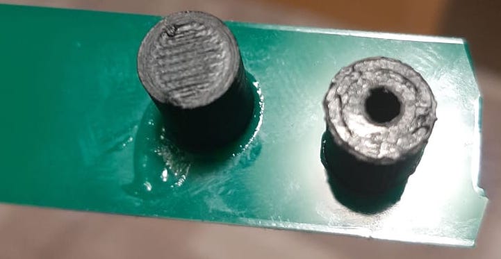
The bond is so strong that no amount of pulling or side shearing by hand made it crack. The ABS has been threaded with a M3 tap and the screw holds really, really well.
As far as I am concerned, the board pillars is a solved problem.
New PCBs
The new PCBs arrived
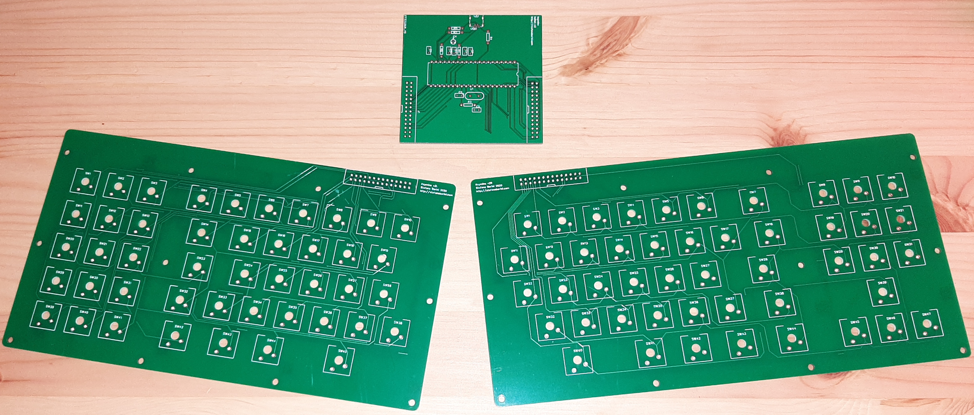
both left and right are completed and need testing. The PCB that will hold the controller is however temporary and will be hosted in a separate box.
Unfortunately, I realised I am a big, fat moron. I created the connector with 28 pins assuming there would be a 28 pins wire-to-board IDC connector, but Amphenol does not make them and the mystical 28 pins connector is not found also on Mouser or RS-Online. Hirose has no 28 either. It’s either 26 or 30. I want to cry now.
The only option I have now is to use a board-to-board connector and jury rig an adapter between a 28 board-to-board and a 30 wire-to-board.